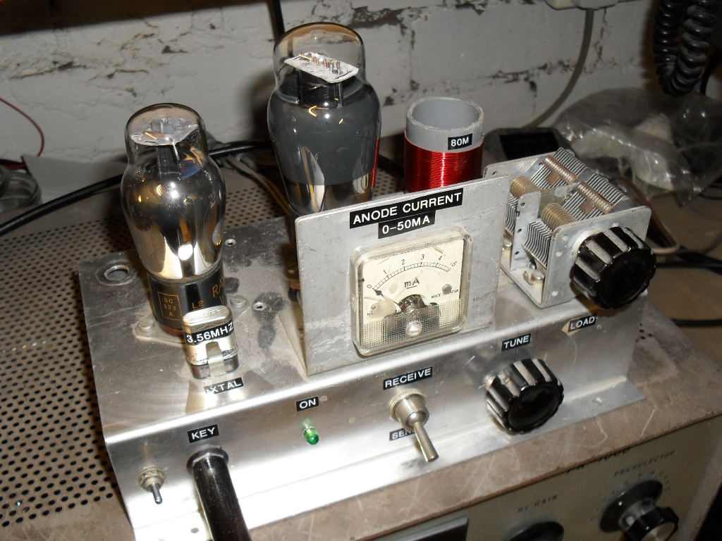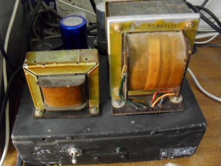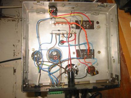

This 80m glowbug is modelled on the 40m / 80m glowbug shown elsewhere on this site. The keying circuit is the same, the only difference here is a triode is used for the oscillator valve. A high / low power switch is incorperated in the screen of the PA valve, 5 Watts low power and 12 Watts high power. The HT is a little high but the transformer in the PSU was free, also being as it is CW duty cycle and a valve, no ill effects have occurred in use ( no glowing anode ) on High power. The large envelope Valves give it a real retro look and it is nice to see the glowing heaters when in use. Although it is crystal controled, I have many suitable crystals for 80m use collected over the years, also you can now buy sets of five 80m xtals on Ebay for approximately five pounds. Some of the crystals are HC49 types fitted into the larger cans in order to utilise the xtal holder. This TX is used in conjunction with a very old Sommerkamp FR-100B valve receiver - a splendid combination. My thanks to Chris G0EYO and Ian M0IDR for kindly donating the valves ( these were originaly to be dismantled for their bases to use as plug in coils but after they tested ok I didn't have the heart to destroy them so here they are! ).
Shown below is an updated circuit diagram, this still gives good keying waveform but eliminates the need for a negative bias supply. Drive from the oscillator valve is rectified by V2 grid/cathode to produce negative bias ( a bit like the old TV line timebase circuits ). Key shaping is provided mainly by the 500nF and 100R. A relay is used for cathode keying of both valves so no high voltages are present on the key, also it allows use of a electronic keyer due to the isolation. The heater supply is rectified/doubled for the relay coil.

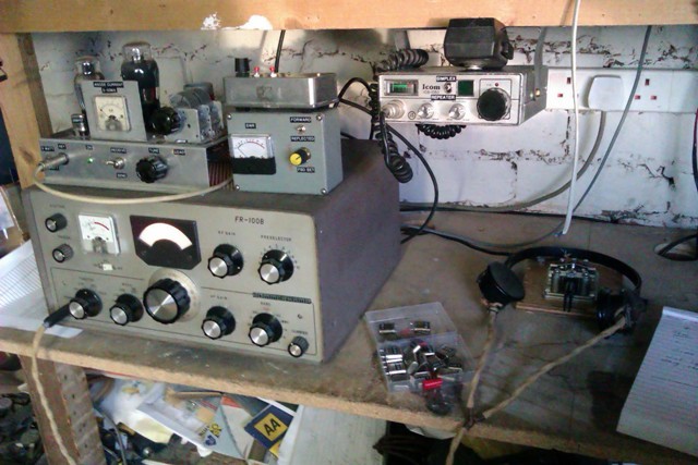
Here is the complete set -up used for Valve QRP day 18/11/2012. Top left 80m glowbug, top right electronic keyer with SWR bridge sitting below this and finally the Sommerkamp FR-100B RX.

Barry Zarucki M0DGQ
HOME